Learn how to build a pump, the main parts and then also optimise the design using CFD Computational Fluid Dynamics.
Learn how to build a basic centrifugal pump and also test blade designs using computational fluid dynamics. You can also download the PDF models of this pump HERE.
SimScale provides instant access to Computational Fluid Dynamics (CFD) as well as Finite Element Analysis (FEA) to over 200,000 users. SimScale has moved high-fidelity physics simulation technology from a complex and prohibitively expensive desktop application to an easy-to-use cloud application accessible through a subscription-based pricing model.
Try SimScale for free: https://bit.ly/2N9Ugmt
Since it's cloud-based, there's no installation required, just sign up on the website for a free community account before purchasing an annual plan. See prices: ➡️ https://bit.ly/2BnbHNA CFD and FEA webinars on HVAC, industrial and turbomachinery: ➡️ https://bit.ly/3diSiuD SimScale Blog on industrial applications and design tips ➡️https://bit.ly/3ddwtwx
SimScale Tutorial: ➡️ https://bit.ly/2Yhws6A
Scroll down to see the YouTube tutorial.
How to do the pushup
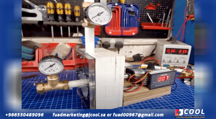
This is the bomb we built. It is a centrifugal type pump made mainly of wood and plastic and is driven by a DC motor with a pulse width modulated speed controller. We then ran the pump at different speeds to see how it worked.
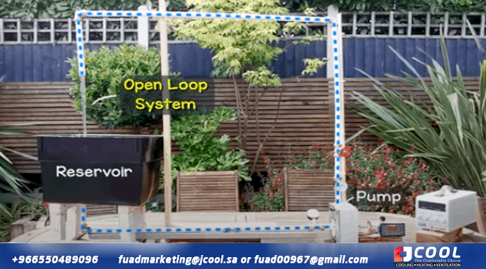
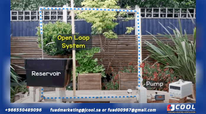
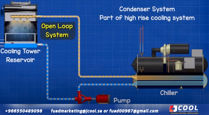
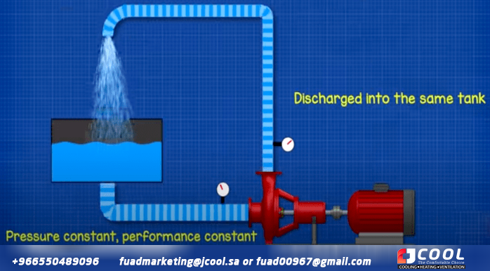
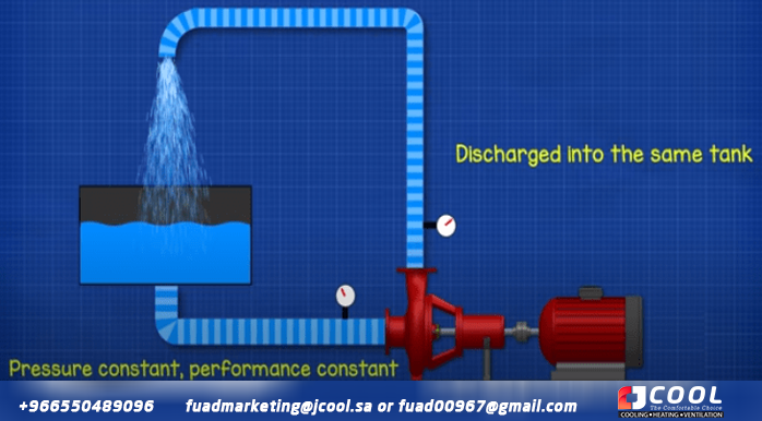
As you can see, this pump is used in an open loop system, circulating water between a tank, the pump, and then back to the same tank. It is a similar configuration to the condenser side of a water-cooled chiller, used to provide large-scale air conditioning in commercial high-rise buildings. Water is pushed through the chiller's heat exchanger to capture unwanted heat from the building and then sent to the cooling tower on the roof, the water is sprayed to release the heat to the atmosphere and the now cooler water it accumulates in the cooling tower pan and flows back to the chiller to capture more heat.
By using this system, we maintain the same suction pressure at the inlet of the pump.
If the pump discharges into a separate tank, the water level at the inlet will change, as well as the pressure, which will change the performance of the pump. To combat this, we would need to refill the same amount of water that was removed. Therefore, it is easier to recirculate the water in the same tank.
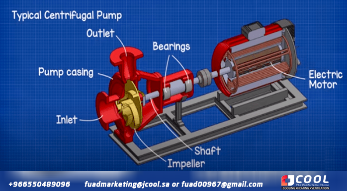
A centrifugal pump is quite simple and has only a few parts. The main ones are the body of the pump. The paddle wheel. The tree. Input and output. Some bearings and an electric motor.
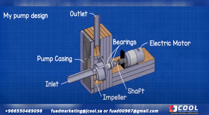
Our design looks like this. We have the pump body, the impeller and the shaft. The Bearing House. The input and output and a direct current electric motor.
The pump design
To keep the design simple, we decided to use readily available materials. For the body of the pump we use marine plywood, it is a strong material that is formed with waterproof glue, it is easy to work with and is often used to build boats. We wanted to be able to see inside the pump as it rotated, so we decided to use a thick sheet of acrylic with a rubber gasket between it and the body of the pump. For the wheel we again used acrylic as it is easy to work with and can be fused with a solvent to form a strong seal. The shaft consists of a stainless steel threaded rod with stainless steel locknuts. We use stainless steel because the impeller will be submerged in water and stainless steel is harder to rust than mild steel. The tubes were made from PVC because it is cheap and has a very low friction factor. The fixtures were mostly copper just because that's what our local store had in stock. To drive the pump, we use a 775 DC motor with a variable speed drive.
Used parts
PWM speed control: http://engineerz.club/pwm-speed-control
775 engine: http://engineerz.club/775-motor
Motor Coupling: http://engineerz.club/dc-motor-coupling
Threaded rod: M8 Stainless Steel Threaded Rod
Wood: 12mm Marine Plywood
Acrylic sheet: 12mm http://engmind.info/acrylic-sheet
DC Power: http://electricl.info/DC-Bench-Power-…
Cup of water: https://amzn.to/2NcnMIh
Hose: 22mm Barrier Pipe PVC
Gasket: 2mm black Rubber
Blade tube: 50mm OD Acrylic tube
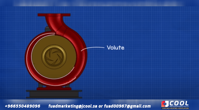
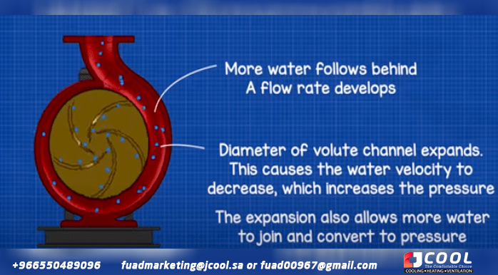
Now that we had selected the materials, all we had to do was design the pump. Centrifugal pumps use a volute, which is an expansion channel around the impeller that converts the velocity of the water into pressure while allowing flow to develop.
We already had 70mm discs for the impeller so we based our volute on that and sketched out a rough volute shape in CAD.
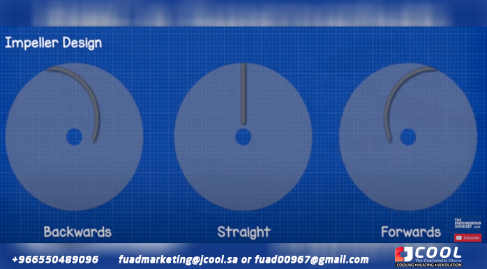
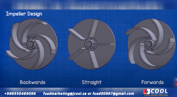
To design the impeller blades, we have 3 main options. The blades can be curved backwards, straight or forward. To keep the design simple to build, we decided to use segments of 50mm acrylic tubing to form the curves of the blades. The dimensions of the tube mean that we can really only mount 5 blades on the wheel. We only use the reverse of this design for the forward curve impeller. For the straight design we will also use 5 blades made from a thin sheet of acrylic.
Performance evaluation of each pump impeller design
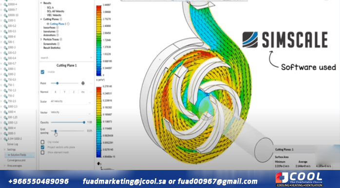
To evaluate the performance of each pump impeller design, we used the SimScale CAE platform, which kindly sponsored this video. SimScale provides instant access to online computational fluid dynamics as well as finite element analysis through an easy-to-use cloud application available through a simple subscription model. You can try the software for free and edit public projects on simscale.com through your community account, or create private projects with enhanced features through your professional, team, or enterprise accounts. If you want to try this software for yourself, click HERE.
So,
after we designed the pump casing and the different impeller designs in CAD,
these are then imported into SimScale for analysis. We don’t know all the
parameters from the start but that’s fine because we can make assumptions and
run different operating points simultaneously to see how the pump would perform
across a wide range. For example, the rotational speed, the outlet pressure,
the flow rate etc.
Once we have setup and ran our simulations, in SimScale, for the
different impeller types, we can then compare the results.
compare results
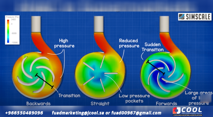
When we compare the results side by side when it comes to pressure - the curved back design has this nice transition from the center to the edges where the pressure is highest so velocity becomes static pressure this is what we need for the pump to work. The straight blade does not have as smooth a transition, low pressure pockets develop in the center which will affect the performance of the blades. The forward-curved wheel has the most dramatic results with large areas of low pressure in the center and sudden changes towards the tips. So from this we can see that the backward curved wheel should be the most effective at converting speed to pressure.
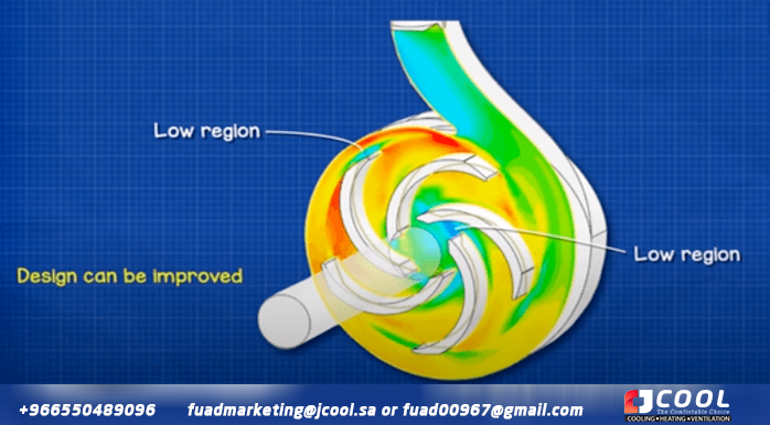
Taking a closer look at the backward-curved wheel, we can see that this design isn't perfect and needs some tweaking. There are regions around both ends of each sheet that can be upgraded to reduce losses.
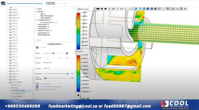
So, if we change the view, we can see that there are areas of concentrated pressure between the blades. This causes recirculation in the pump. We could use a cover to reduce this and improve performance and we can run it again in the simulation to quantify its impact.
To actually design this design, we would run several simulations with different blade thicknesses, different blade angles, different impeller diameters, and also the number of blades to find the optimal design. But this will suffice for now, as this is a simple project.
Building
To build the pump I took sheets of wood 145 mm wide, 170 mm high and 12 mm thick.
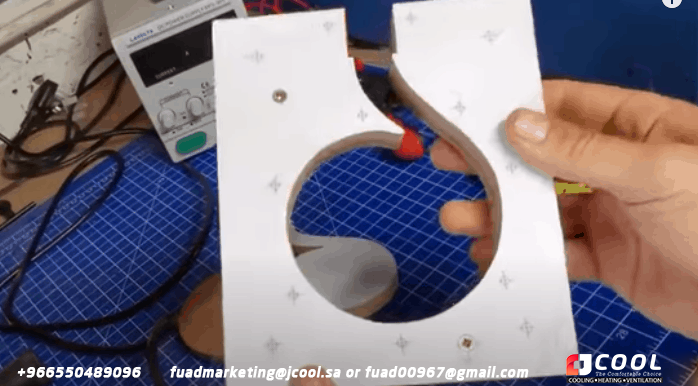
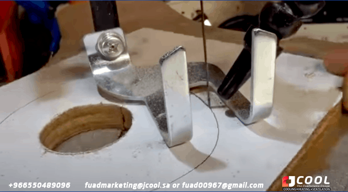
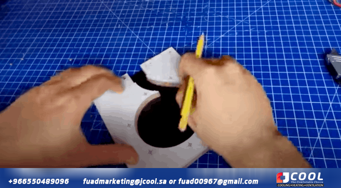
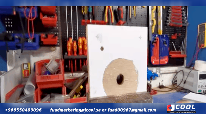
We print our parchment design, then use a paper cutter to cut the paper to size and glue it to the wood to use as a template. To save time, we screwed two sheets together, then used a jig saw to carefully cut out the center of the template. With the center removed we can see how the volute of the bomb is formed.
We then glued the template for the back plate to another sheet of wood and used a hole saw to remove part of the inner segment. This allows us to insert the saw blade and cut the center.
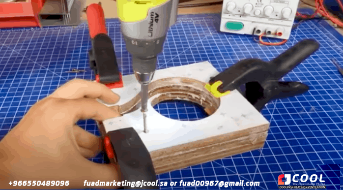
After the main blows were made to the pump casing, we used strong wood glue to form a seal between each of the sheets and let them cure. Once it was ready, we screwed all three sheets together and used a file and sandpaper to ensure a smooth internal surface.
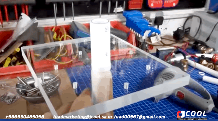
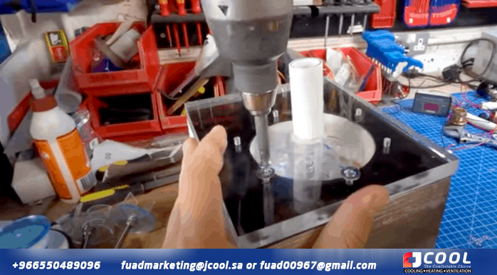
For the cover, we cut out the paper template again and glued it to a clear acrylic sheet. This will bolt to the body of the pump, so we drilled a series of holes with a bit that was slightly larger than the diameter of the bolts. We then used a 22mm hole saw to cut a hole in the material for the PVC inlet pipe. To try and ensure a perfect fit, we took some wood and filed it down until it would fit inside the PVC pipe. We then heated the pipe with a heat gun until it could be released and pushed the front cover over it to form a seal. It was then covered in hot glue inside and out.
Between the front casing and the volute of the pump we need a rubber gasket, for this we use a 2 mm thick rubber sheet, on which we draw the outline of the volute, then we seal it cut to see the inside, while sealing around the edge.
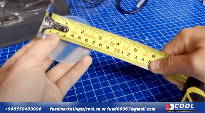
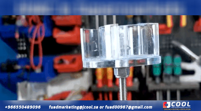
For the wheel, we took a 70mm diameter acrylic disc and found the center using the center gauge on the combo set. Next we drill the disc with a bit of the same diameter as the threaded rod.
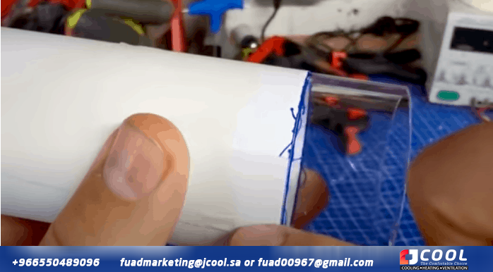
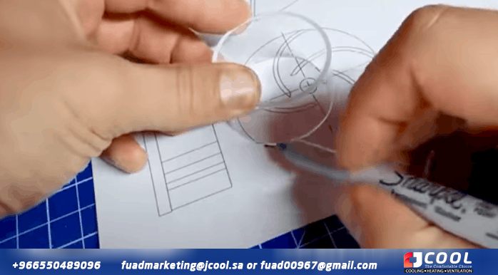
To form the blades, we took a 50mm acrylic tube, then wrapped it tightly and glued white paper around it, making sure the edges were flush. The blades are 20mm high so we measure this on the tube and use the edge of the paper to draw a line around the circumference. We then cut along the line to remove the section we needed, then placed that segment over the wheel designs to mark the start and end points. These segments are simply cut from the tube to form the blade.
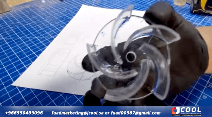
With all the leaves now cut, we take some solvent and apply it to the base of each leaf before moving the leaf into the required position. The solvent melts the materials so that they fuse together and form a very strong bond.
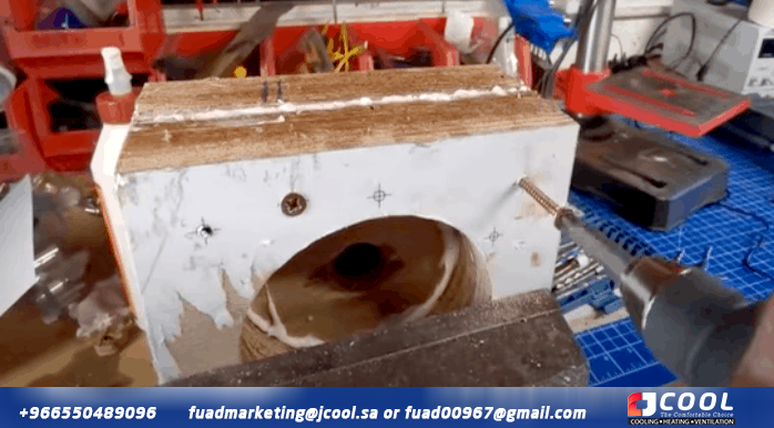
For the bearing housing, we cut out the CAD template again and glued it to a piece of wood. Once this was taken care of, we attached it to two more pieces of wood and used a hole saw to cut out the hole that the bearings will go into. Then we glued the wood together and also attached them with screws.
Once the glue dried we used a file to remove the excess glue and widen the hole so the bushings would fit snugly. We then fit the two bushings and a spacer onto the threaded shaft and force them into position.
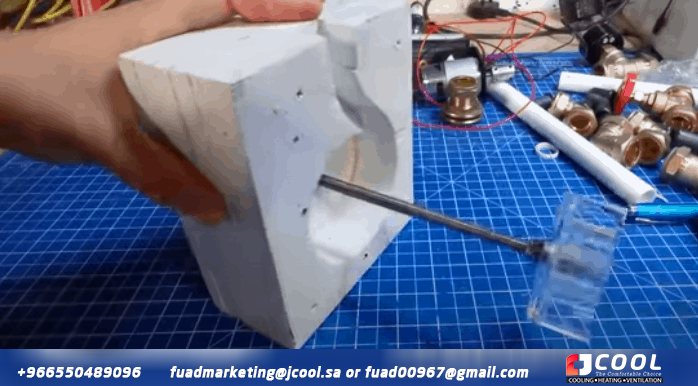
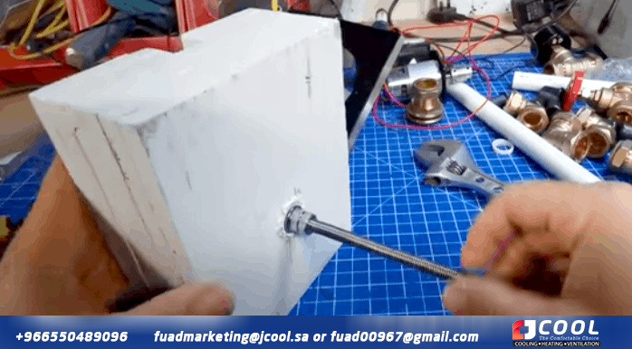
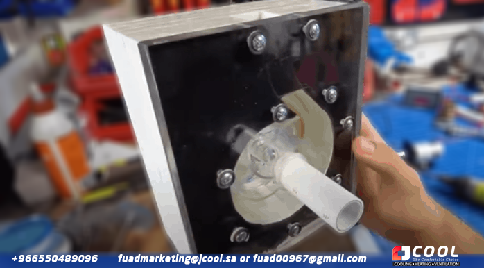
For the axle, we use stainless steel threaded rods along with flanged lock nuts to hold the wheel in place. With the blade temporarily installed, we can see that it rotates well and there is a small gap between the blade and the supporting wall.
The volute and bearing housing were glued to form a seal between the materials, then held together by extra-long screws. The wood was coated with a white primer and a few coats of waterproof putty.
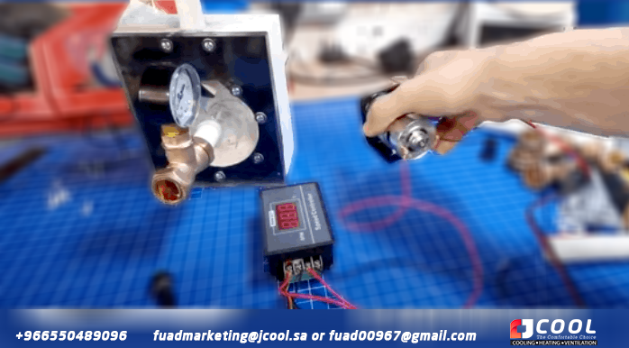
For the outlet, we simply inserted the 22mm tube and added a piece of rubber to create an airtight seal, then covered them in hot glue to hold them in place. Then we install a pressure gauge at the inlet and outlet of the pump to take some measurements.
 |
| 775 DC motor driven pump |
The pump is driven by a 775 DC motor that is controlled via a PWM speed controller. The other two wires then connect to the bank's power supply. A simple dial controls the speed of the motor. These parts were then mounted to the rear of the engine and connected to the shaft via a coupling.
By the way, we've covered how DC motors work– look HERE as well as the pulse width modulation clock HERE.
bomb test
 |
| open circuit system |
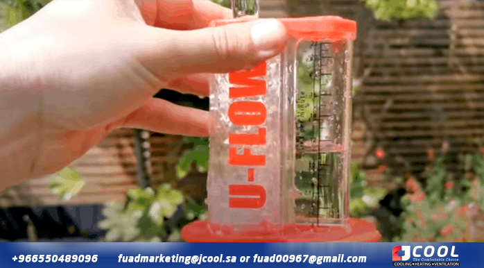
To test the pump, we did a simple open-loop setup. We have a water tank and a pvc pipe that goes through an elbow, through a ball valve, and then to the inlet of the pump. The pump is driven by the DC motor and speed controller, which is powered by the bank power supply. The pump outlet then goes up, goes through a few curves, and back to the supply tank. We then use a cup of water to measure the flow.
 |
| measure flow |
Now, as we can see, the pump is working fine. We managed around 16 liters per minute at maximum flow, but the tools and methods we used to test the pump were not accurate enough to compare with our simulations.
Firstly, the gauges did not indicate any pressure, which makes evaluating the performance of the pumps almost impossible, so it will have to be done by hand and with big assumptions. There were a few small leaks from the pump, most of which could have been plugged with waterproof grease, but unfortunately we didn't have any at the time. The water cup isn't exactly a precision instrument, but it's all we've got, so we'll just have to. The big problem we faced was cavitation.
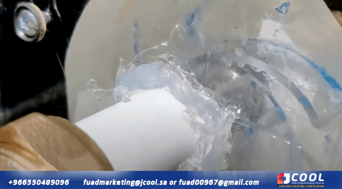
As you can see here there is air inside the wheel and the rate of cavitation increases with speed. This air is drawn in from small spaces around the intake tube due to the region of low pressure created in the eye of the wheel. We also believe that the return water that falls into the tank causes small bubbles in the feed. Now this is a working prototype so issues like these are to be expected and now that we know the issues we can fix them in a future model.
How did the pump and turbines work?
 |
| Performance |
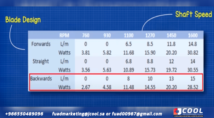
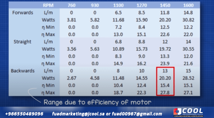
So how did the pump and boosters work? In all designs we can see that no flux has developed in the system until the shaft reaches approximately 1000 rpm. By comparing the results of the three different wheels, we can see that the backward curved wheel was the most effective. This is because for every watt of electricity consumed, it was able to convert it into more useful mechanical work, resulting in higher performance compared to other designs.
The least efficient design was the forward curved impeller, closely followed by the flat vane impeller.
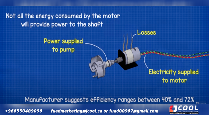
To assess the efficiency of the pump, we try to take into account the losses of the electric motor. From the manufacturer's data it shows that the minimum efficiency is around 40% and the maximum is around 72%, but both figures are calculated under no-load conditions and our motor is obviously under load. But we will only use these numbers to get a rough estimate.
Taking this into account, we see that the reverse curve turbine had a maximum efficiency range of between 15.4 and 27.8%. Straight blades were between 13.3 and 23.9% and forward curved blades were between 12.5 and 22.57%. These are only approximate numbers, as there are many inaccuracies in the data and measurements and we know that if you enter the wrong data, you will get wrong results.
Do you need help maintaining and repairing an air conditioner?
It's hard to keep cool when the air conditioning isn't working. Whether it's repairs, air conditioning, regular maintenance, or assistance with choosing your new unit, JCOOL professionals can keep you comfortable all year
Jamjoom Cooling Systems Factory (JCOOL) products (condenser coil - evaporator coil - heat exchanger - air conditioning - cold evaporator - cooler - industrial air cooler - tube bundle - air heat exchanger)
Make a reservation immediately with the maintenance team before the summer heat intensifies.
Let us help you with a lot of maintenance and installation work on your next project.
To request the service: -
Jamjoom Cooling Systems Factory
Jeddah - Second Industrial City - Street 49
WhatsApp +966 550 489 096
fuadmarketing@jamjoomarcool.com
fuadmarketing@jcool.sa
Fuad00967@gmail.com
Eng/ Abu Hussam
#heatExchangers #condensers #evaporators #coolers #coils #airDucts #chiller's #jcool #Saudi_industry #cooling #ventilation #radiators #jcool #jamjoomCoil #jamjoom_cooling_systems_factory #jamjoom #saudiArabai #coolingtowers #cooling_tower #coolingcoils #heat_exchanger #heatexchanger #coolingsystems #cooling #chiller #hvac #jamjoom_hvac #jamjoom_cooling #global_cooling_tower #Brand_Saudi_Arabia #made_in_Saudi_Arabia #🇸🇦




Comments
Post a Comment